NSX Packet Walks - VLAN Bridge
by vAntMet
This is the fourth post in the NSX Packet Walks series. You probably want to start at the first post.
Up to now we have focused on the traffic from one VM to another VM somewhere within the NSX system, as well as how traffic moves between physical hosts. But what if you’re data centre isn’t 100% virtualised? Can you still use NSX? What are the constraints? This post will look at this question.
There are a few reasons why we may have physical machines still within the network, which must be accessed from within the NSX environment, but the two most common are Legacy applications that will not support being virtualised (say Sparc/Solaris banking software) and high performance systems that use the full capacity of the hardware and so are not virtualised (huge database systems fall into this category, although it’s a category that’s shrinking all the time). In these cases we need a way to connect the two sides, the VXLAN on the NSX side, with the VLAN on he physical side. This is done using VXLAN-to-VLAN bridging, also called L2-Bridging or the L2-Bridge.
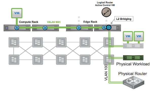
Consider the following image, taken from the VMware NSX Design Guide version 2.1 (fig 35)

The diagram shows how the physical workload can be connected to a VLAN, which can then be connected to one (although in reality multiple) but not all hosts. We don’t need to span the VLAN to all of our compute racks just to get the VM access to the VLAN. This is a major advantage.
We would probably connect the VLAN to all of the servers in the Edge rack, to ensure that it remained accessible in case of fail over. We choose the edge rack so as not to pollute the standardisation of the compute racks. In small environments, this is less of an issue.
We can also see from the diagram that the L2-Bridging is done from the virtual distributed router, and not from the Edge Router VM. Finally, we can see that the host that is used for the L2-Bridge, is the one running the “Active Control VM”.
Active Control VM
The DLR (Distributed Logical Router) is actually made up of two parts. The VIB that is installed to each host when the cluster is instantiated for NSX, and the DLR Control VM. The role of the Control VM is to be the control plane for the distributed logical router. It is here that LIFs get defined and pushed out of the DLR instanced on the hosts. It is also here that BGP or OSPF is instantiated to communicate with the Edge Router VM(s). Finally it regulates communication with the Controller Cluster, and Management VM so that each host isn’t needing to be in constant communication with either, reducing load.
The DLR Control VM is in an Active/Passive pair, and is usually placed in the Edge Cluster (precisely so that the L2-Bridging can be placed in the edge cluster).
Whichever DLR Control VM is active is referred to as the Active Control VM. The active control VM picks a specific DLR to perform the bridging action.
Bridging Constraints
There are a few caveats with L2 Bridging.
Firstly the bridging s a 1:1 mapping. You cannot have 1 VLAN bridged onto two VXLANs or vice versa. This may impact how you can create Virtual Networks without re-iping if you are moving from a physical environment.
Secondly, as the Bridge instance is decided by the DLR Control VM, the bridge instance is tied to a specific host. This will usually mean there is a bottleneck for traffic at the bridge.
Different bridge instances can be tied into different hosts, which improves this bottleneck a little, but also makes the configuration more complex. Default behaviour is to place the Bridge instance on the host with the control VM as in the image, but it can be chosen during configuration, on a case by case basis for each bridge instance.
Although the Control VM decides which DLR instance performs the bridging, no data flows through the control VM. It is all handled by the VIB at the host.
Packet Walks
Once bridging is in place it is easy to see that the DLR will know which BUM traffic needs to be sent over the bridge, due to having an IP address on the VLAN. From the bridge instance, the BUM traffic works exactly as in a traditional environment out to the physical box and back. So we still have the advantage that BUM traffic does not flood the network, and only moves to the Edge rack, to move out into the wider LAN.
Next time we will discuss North-South traffic and tie up the series.
tags: nsx