NSX Packet Walks Continued
by vAntMet
This post is a continuation of the last post where I discussed a very simple virtual network, and a very simple VXLAN environment. If you haven’t already, you will want to read that post first. In this post I’m going to step it up a gear and introduce a virtual distributed router to the mix. This is a key part of NSX and the ability to create virtual networks on the fly without waiting for provisioning externally. It also makes for an interesting thought process when the “router” is distributed across all hosts.
Again we will start with a very basic network, to get some concepts out of the way, then we will move to the NSX version.

The above diagram shows two VMs this time on different VLANs separated by a router. Now is probably a good time to make a small diversion to talk about where the decision about what device to send a packet too is made. This doesn’t matter to the vast majority of cases, as with just a single NIC the outcome of the decision process is the same. But as soon as you get devices with multiple NICs, this starts to get interesting. Last time we discussed devices on the same VLAN, the same subnet, the same broadcast domain. These three terms are often used interchangeably, and are indeed usually kept the same to make life easier. This meant that the OS within the VM, when sending a packet to VM2 knew to send an arp to discover that VMs MAC address to use for all further communication. The decision tree though, started a good ways before that.
When the OS gets the message from the Application that a packet needs to be sent to another device it first looks at the IP address of the destination machine. It compares this to it’s ARP table, a list of MAC addresses, and IP addresses, and Interfaces they have been seen on. If the IP address of the other machine exists in the ARP table, then the packet can be addressed to the correct MAC address and sent out of the correct interface. If there is no entry, then it must work it out. It then compares the IP to any and all known IP subnets connected to interfaces on the machine. If the IP address is in the same subnet as one (or more) of the interfaces, then it matches to the most restrictive subnet that contains the IP, and sends an ARP out of that interface.
If the IP address doesn’t fall into the subnet of any of the subnets on the machine, then it is sent to the Default Gateway MAC address instead. The Default Gateway must always be in the subnet of one of the interfaces on the machine.
So, now we can look at the diagram again. We can assume that each VM has “router” as it’s Default Gateway.
The two VMs boot. The have a mac address, and an IP address configured. Just for fun we’ll assume they each have the IP address of the other in their hosts file, so we don’t have to involve DNS. VM1 wants to send a packet to VM2. Following the decision logic outlined above, VM1 ‘knows’ that it cannot send the packet direct to VM2 and must instead send to the interface of it’s default gateway.
- VM1 sends an ARP packet to FF:FF:FF:FF:FF:FF, with the IP address of the default gateway. This is passed via the portgroup into the vSwitch. The vSwitch at this point stores the gateway’s MAC in it’s CAM Table and IP addresses in it’s fib table.
- the vSwitch passes the packet to the physical switch. The physical switch stores the IP and MAC of VM1 along with the port the packet entered on.
- the first physical switch either broadcasts the packet, or more likely already has the IP/MAC combination in memory and passesd the packet to the router.
- the router replies with it’s ARP reply back up to the VM.
- VM1 then sends the original packet to VM two, addressing the packet with a destination MAC address of the Default Gateway.
- The packet flows to the router, which then inspects the packet, and does a similar look-up to the one the VM OS originally did. That is it compares the destination IP to those of the subnets it is connected to, and posts the packet out of the correct interface. If it already has the IP/MAC details in it’s arp table then the packet will be unicast, addressed to the correct MAC address. If not it will be broadcast, addressed to FF:FF:FF:FF:FF:FF. Either way it will be seen by VM2 which can reply. If the router doesn’t have an entry for the correct subnet, and also doesn’t have a default gateway. The packet is dropped.
This is about the simplest conversation that can happen over a routed Ethernet network.
Now let’s step it up a gear.
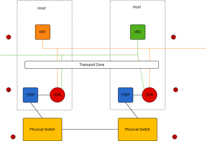
Here we have a very simple, routed NSX network. I am assuming one transport zone, set to “unicast mode”, with two logical networks (say VXLAN 5001 in orange and VXLAN 5002 in Green), VM1 is connected to 5001 and VM2 to 5002.
When a cluster is prepared for NSX, there are three initial modules that are added into the kernel of each ESXi host. The first of these, we have seen is the tunnel end point, the VTEP. The second is the Virtual Distributed Router (VDR) and the third is the Virtual Distributed Firewall (VDF). We wont worry much about the firewall module in this series.
The VDR gives us a great boost, because we no longer need to funnel all inter-VLAN traffic up to a central routing point (usually a TOP of Rack switch, or core router). We can do that routing within the hyper-visor of the hosts. This means that so called East-West, or server to server traffic can have much shorter and more direct routes, reducing latency, and bandwidth utilisation. This also removes us from requiring VLANs to be created on physical switches for every virtual network, and the work involved in adding VLANs to routing tables. We can dynamically create networks and add them to the VDR without any need to touch the physical switches or routers.
Although the diagram appears to have two routers, both connected to our two virtual networks, they actually form one single logical router. Any changes to configuration, or CAM/FIB tables are re-distributed by the network controllers to all other instances. We can consider the VDR as a single router with, in this case, two Logical Interfaces (LIFs). Each LIF has a MAC address. Thought about like this, the logical setup is actually even simpler than network we looked at above.
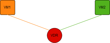
Looked at from this point of view, VM1 will send the packet addressed to the MAC address of the router’s LIF on VXLAN5001, and the IP address of VM2. The logical router will take that packet and push it out of the interface on VXLAN5002, this time definitely as a uni-cast packet, as the logical router will have been informed of VM2’s IP and MAC addresses. VM2 will receive the packet, and the reply will be int he reverse direction.
In reality, the packet is passed by the logical switch to the VDR on host 1. The routing process is done, and the packet is placed on VXLAN5002, and passed to the VTEP. The packet is then passed to host 2, where the VTEP passes the packet up to the logical switch and then to VM2. The return packet, begins it’s life on VXLAN5002, and is passed to the logical router on host 2, where it is re-transmitted onto VXLAN5001 and passed to the VTEP on host 2, etc etc. The Logical Router Instance used is always the closest to the VM that creates the packet. This seems to me to be the only logical way the process can work with the logical router having one MAC address per LIF. To work any other way, it would need 1 MAC address per host, per LIF, and it would get very much more complex, very quickly.
tags: nsx